

Rubber Profile Extrusion Line Innovations That Boost Production Efficiency
2026-11-16
Most rubber profile extrusion lines can push material through a die. Far fewer can hold tight tolerances at higher line speeds without driving scrap rates up. That gap is where the latest innovations—smarter temperature control, redesigned screw geometry, and faster tooling changeovers—are quietly changing the economics of rubber processing. At SFC, these improvements aren't theoretical; they show up in shorter setup times, more consistent profiles, and fewer rejected meters. Here is a closer look at what is actually moving the needle.
Preheating Systems That Shorten the Path to Stable Output
Bringing a cold instrument up to temperature usually means waiting through a long stretch of drift before readings settle. Preheating systems take a different route by targeting the thermal mass that actually matters, warming only the sensing element and its immediate surroundings instead of the entire enclosure. That focused warm-up cuts the phase where output wanders and lets the device reach a usable state with far less idle time.
The real difference comes from where the heat goes, not how much power is applied. A carefully shaped preheat loop feeds just enough energy into the front end to keep the thermal gradient shallow, avoiding overshoot while finishing quickly. Once the critical zone is close to its operating point, the main control loop takes over without wrestling a large temperature error, so the output settles sooner and stays there through normal use.
In day-to-day operation that shorter warm-up path means fewer discarded readings, faster readiness after power-on, and less need for repeated zero or span corrections. It is a subtle change, but it reshapes how the equipment behaves in those first minutes when stability matters most.
Die Design Updates That Reduce Tearing at Higher Throughput
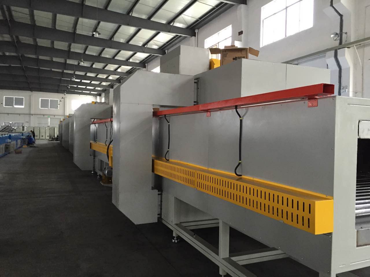
Running a die at higher throughput usually exposes weak points that slower speeds never reach. The first place I look is where the material has to accelerate or change direction over a short distance; that is where surface strain concentrates and a small inclusion or uneven grain flow turns into a tear. Adjusting the inlet geometry so the reduction happens over a slightly longer zone, rather than forcing the same work into a tighter corner, often lowers the peak stress enough to keep the strip intact without sacrificing output.
Another update that helps is reworking the bearing lengths and relief angles in the exit zone. At higher speeds, the material leaving the die is still carrying more heat and is less tolerant of a sharp transition back to ambient conditions. A modest increase in the corner radius at the land exit and a smoother blend between the land and the relief can stop the edge from dragging and reduce the small tensile spikes that eventually become tears. Where the cross-section changes shape, adding a short transition land instead of a single step gives the metal a chance to redistribute its flow, so the thinner sections do not get stretched past their forming limit.
If tearing persists after those geometry changes, the next step is to map the local thinning across the profile. Measuring thickness at a few points along the tear path usually shows whether the problem is caused by entry-side compression or exit-side dragging. Shifting the bearing length slightly on the side that tears, or adding a small taper in the opposite wall, can redirect flow just enough to balance the section. These are not large changes, but in practice they matter more at higher throughput than at standard speeds because the process window narrows once the material is moving faster and cooling rates become less uniform.
Automated Line Speed Adjustments Based on Live Weight Measurements
A fixed chain speed is usually a compromise set for the heaviest bird or cut the line might carry. That leaves the line moving slower than necessary for much of the shift. With live weight measurements taken from a short in-motion scale section, the control system adjusts the drive in small increments: heavier product eases the belt down, lighter product brings it back up within a defined speed band.
The effect shows up most clearly at transfer points and grading stations. Instead of sudden slugs of product arriving after a heavy run, the flow evens out enough for trimming and sorting crews to keep a steadier rhythm. The logic still has to account for signal noise and brief gaps between items, but once the averaging window and speed limits are set correctly, the line tends to feel less like it is being controlled and more like it is responding to the product on its own.
Vacuum Calibration Zones That Lock Profile Shape Earlier
The real benefit of pulling vacuum early is that the extrudate stops being a suggestion and starts being a fixed cross-section before gravity and melt elasticity have time to argue with it. In the first few centimeters after the die, thin walls can sag, inner webs can drift, and corners can round off just enough to ruin a fit. A well-placed calibration zone applies negative pressure right where the surface is still soft enough to be corrected, so the profile is locked into its intended form while there is still room to make adjustments.
Rather than relying on a single strong vacuum slot, many lines use short zones with separate pressure control. The first zone does the heavy work of pulling the hot surface against the calibrator, but at reduced force to avoid dragging or tearing the skin. The following zones hold the shape while the outer layer begins to chill and gain enough stiffness to survive the water bath. This stepped approach lets the profile settle into the tooling without the sudden jump that often shows up later as diagonal stress marks or uneven gloss.
Locking the shape earlier also changes how tolerant the downstream process can be. Once the outer walls are set, cooling becomes more predictable because water no longer acts on a moving target. Hollow chambers and undercut details benefit the most, since they lose internal support the moment they leave the die. By using the vacuum zones to freeze the geometry before the cooling pulls it out of true, the line becomes less sensitive to small speed changes and material lot variation, which is often what separates a stable production run from a day spent chasing dimensions.
Quick-Change Crossheads That Make Short Runs Practical
Short runs often stall before they even start because changeover eats more time than the actual extrusion. A crosshead designed for quick change removes that bottleneck: a few loosened fasteners, a cartridge or split design that opens without disturbing downstream tooling, and the old tip and die set slides out. There is no need to pull heaters or fight seized threads just to go from one jacket compound to another.
The real benefit shows up in scheduling. When a quick-change crosshead can be stripped, cleaned, and refitted in under ten minutes, a run of a few thousand feet no longer has to carry the burden of an hour-long setup. Operators can sequence colors and materials back-to-back, use smaller batch sizes, and still keep the line moving. That makes short runs practical from a cost standpoint rather than something to avoid.
One detail often overlooked is repeatability. A well-built quick-change crosshead locates the tip and die on fixed registers or keyed components, so the setup goes back to the same concentric position after every change. That cuts the trial-and-error adjustment that usually follows a teardown, reduces scrap in the first few hundred feet, and helps the next shift trust the tooling. For shops running multiple profiles or compounds in a day, that consistency matters more than the time saved.
Cooling Section Upgrades That Keep Shrinkage Predictable
Uneven cooling has a way of hiding until the film hits the shrink tunnel. Upgrading the cooling section changes that by narrowing the temperature band across the web. High-velocity air bars with individually adjustable zones, repositioned after a hard look at existing flow patterns, pull heat out at a more consistent rate. When the sheet leaves the section with less internal stress frozen into it, the shrinkage values stop drifting between shifts.
Roll temperature control matters just as much as air movement. Older chill rolls often develop cool spots or lose contact pressure, and those small differences show up later as tight or baggy edges. Replacing worn rotary unions, balancing water flow, and adding polished sleeves keep the surface temperature uniform where the material actually touches. The result is a more repeatable orientation profile, so downstream shrink performance becomes a process setting rather than a daily guess.
Feedback loops close the gap between equipment capability and real production conditions. Installing infrared sensors at the exit, combined with automatic trim of air volume and water temperature, lets the line correct drift before it becomes off-spec product. This shift from reactive adjustment to continuous control keeps shrinkage predictable even when ambient conditions or line speeds change.
FAQ
Upgraded screw geometry and barrel venting tend to move the needle most. A screw that combines deeper feed channels with a longer, shallower metering section can push more compound without raising stock temperature too much, while improved venting removes trapped air before it creates porosity in the profile. In many plants, those two changes alone allow a 15 to 20 percent speed increase on dense profiles.
Instead of relying on one long water trough, newer lines use staged cooling with separate temperature zones and air knives between stages. The profile is cooled just enough to hold shape, then the surface is dried briefly and moved into the next zone. This pulls heat out faster without shocking the rubber, so the line can run at higher take-off speeds while keeping dimensional stability.
Closed-loop control on melt pressure and haul-off speed is a big one. When the system continuously adjusts screw speed and puller speed to hold a set pressure at the die, you get far less variation in cross-section. Operators spend less time making manual corrections, and scrap from off-spec startup lengths drops noticeably.
A well-designed die does more than shape the profile. It balances flow so the compound exits evenly across the cross-section, which prevents edge tearing and uneven swell. Using low-friction coatings on the die land also reduces build-up, so you change dies less often and keep running longer between cleanings.
Yes, gravimetric feeding systems that dose compound by weight rather than volume make a clear difference. They keep the extruder barrel filled consistently, which steadies pressure and reduces pulsation. That stability lets the line hold tighter tolerances at higher speeds, especially with softer or stickier compounds.
Automatic splice detection and laser-based profile measurement are two practical examples. The laser system checks dimensions continuously and can trigger an alarm or adjust the haul-off before a bad section gets very far. Meanwhile, automatic coilers or cutters synchronised with line speed remove the need for constant manual handling, which reduces bottlenecks at the end of the line.
Many newer lines have condition monitoring built into gearboxes and barrel heaters. Vibration sensors and thermal imaging catch bearing wear or heater drift early, so maintenance can be scheduled during planned stops instead of reacting to a breakdown. Quick-change barrel liners and modular screw elements also shorten the time needed for compound changes.
Barrel heating zones with better insulation and regenerative drives on the extruder and haul-off are common. Instead of wasting braking energy as heat, the drives feed it back into the line or site supply. Combined with insulated heating and cooling zones, energy use per kilogram of finished profile often falls by 10 percent or more.
Conclusion
Modern rubber profile extrusion lines have moved beyond incremental tweaks. One of the more overlooked changes is preheating, which brings the compound closer to processing temperature before it ever reaches the screw, cutting the time needed for stable output after startup. That early thermal consistency works alongside reworked die geometry. Instead of accepting edge tears when line speed climbs, tooling now uses adjusted land lengths and flow channels that reduce localized stress at higher throughput. Together these upstream refinements let operators hold tighter tolerances while running faster. Meanwhile, line speed no longer depends on an operator's feel; live weight measurements feed back into the control system, so the haul-off adjusts automatically when the extrudate gains or loses mass, keeping meter weight consistent without constant manual intervention.
Downstream, vacuum calibration zones have become more aggressive, pulling the rubber profile against the sizing surfaces sooner so the shape is locked before it has a chance to sag or swell. This earlier geometry set makes subsequent cooling far more predictable, especially where shrinkage has traditionally caused batch-to-batch variation. Cooling section upgrades add staged water and air quenching, which tempers the profile more evenly and prevents the late dimensional drift that shows up only after final cutting. For plants that handle frequent product changes, quick-change crossheads reduce the penalty of short runs. Instead of a lengthy teardown, tool heads and inserts can be swapped fast enough that smaller batches become economically viable, giving processors more flexibility without sacrificing the consistency gained from the other line improvements.
Contact Us
Contact Person: Chen Zhengwei
Email: [email protected]
Tel/WhatsApp: +86-13963975727
Website: https://www.sfcrubbermachine.com