

Custom Metal Lathe Mastery: Craft Precision Parts with Expert Techniques
2026-07-31
Mastering the metal lathe isn't just about turning stock—it's about turning possibilities into perfectly engineered reality. Yet, for many machinists, reaching that level of precision demands more than off-the-shelf solutions. Custom techniques and the right partner can bridge the gap between standard output and flawless craftsmanship. In this post, we explore expert strategies for producing bespoke precision parts, revealing how WINNRUI CNC turns complex challenges into your competitive edge. Get ready to elevate your lathe work from routine to remarkable.
Selecting the Right Stock for Precision Machining
Selecting the right stock material is a quiet art in precision machining. You can't just grab any bar of metal off the shelf and expect micron-level results. The material's internal structure matters—how it behaves under a cutting tool, how it holds dimensions after you’ve shaved off half its weight. Some alloys fight you every step with chatter and built-up edge, while others cut like butter but then warp overnight. It’s the balance between machinability and stability that separates scrap parts from sellable ones.
Aluminum, for instance, gets a lot of love because it’s easy on tools and wicked fast to machine. But not all aluminums are equal: 6061 is the workhorse, good for general jobs, while 7075 offers more strength but can be a bit more finicky. Steels demand respect—4140 pre-hard gives you toughness without being impossible to cut, but if you need corrosion resistance, stainless grades like 303 or 316 step in, each with its own personality in the machine. And when metal won't do, engineering plastics like PEEK or Delrin can shine, especially when weight or chemical resistance throws metals out of the running. The trick is matching the material's character to the part's real-world demands.
Beyond just the grade, the form of the stock matters too. Extruded bars, rolled plates, or cast billets all start with different stress patterns locked inside. A thick plate sawed from a larger block might move more during machining than a carefully stress-relieved blank. Sometimes the extra cost of a forging or a custom near-net shape pays for itself by reducing machining time and scrap. Smart shops don't just pick a material; they pick the whole supply chain behind it.
Setup Strategies for Stable and Accurate Cutting
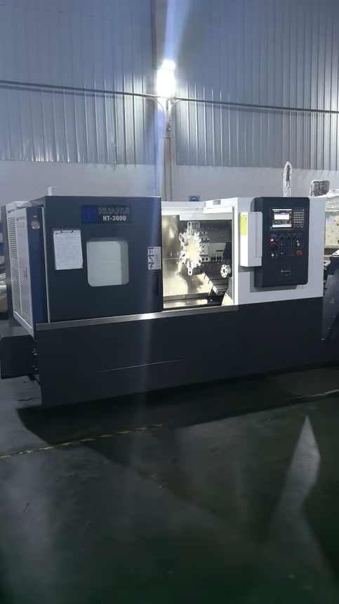
Before making a single cut, it's worth spending extra minutes on machine and material preparation. A rigid setup starts with a clean, flat work surface and properly maintained workholding. Inspect vises, clamps, and fixtures for wear or debris that could introduce play. Bolt everything down firmly, but don't overtighten to the point of distorting the part. If you're using soft jaws, machine them in place on the actual fixture they'll be used with—this automatically corrects for any spindle or table misalignment, giving you near-perfect concentricity and contact.
Tool selection and stick-out length have a surprising influence on stability. A general rule is to keep the tool as short as possible while still reaching the needed depth; every extra millimeter invites deflection and chatter. For finishing passes, a slightly larger tool diameter with more flutes can dampen vibration, but make sure your machine has the torque and rigidity to push it. Damping bars, shrink-fit holders, and hydraulic chucks are excellent investments when you're chasing micron-level tolerances. They reduce overhang and improve dynamic stiffness far more than standard collet chucks.
Finally, tailor your cutting parameters to the entire system's natural frequencies. Instead of blindly using catalog speeds and feeds, listen to the sound of the cut and feel the machine for any harmonic buzz. A small RPM adjustment—sometimes as little as 5%—can shift the tooth-passing frequency away from a resonance, instantly smoothing the finish. Combine this with climb milling wherever possible and use light radial engagement in difficult materials. A stable process sounds clean, leaves consistent tool marks, and reduces insert wear dramatically.
Tool Selection and Geometry for Fine Finishes
Achieving a fine finish isn’t just about the machine’s capabilities—it starts with picking the right tool geometry. A sharp, honed cutting edge with a large nose radius often works wonders on delicate contours, minimizing scallop height without sacrificing surface integrity. For intricate 3D surfaces, ball end mills with variable helix angles reduce chatter, letting the tool glide almost silently across the workpiece.
Don’t overlook the helix angle when chasing that mirror-like sheen. High helix tools lift chips quickly, pulling them away from the cutting zone before they can scratch the freshly machined surface. Pair this with a fine-grain carbide substrate and a smooth PVD coating like AlTiN or DLC—the combination lowers friction, resists edge build-up, and keeps the finish consistent from the first part to the hundredth.
Sometimes the secret lies in tip geometry tweaks you can’t see. A slight radius at the insert land or a wiper flat behind the primary cutting edge acts like a tiny burnisher, ironing out microgrooves as it passes. For finish boring, a high-positive rake insert with a polished chipbreaker keeps material from gumming up while delivering tight tolerances straight from the tool to your gauge.
Controlling Tolerances with Advanced Measuring Techniques
In precision manufacturing, even a deviation of a few microns can spell the difference between a flawless assembly and a costly failure. Advanced measuring techniques have transformed how we maintain tight tolerances, moving beyond simple calipers to systems that capture complex geometries in real time. Laser interferometry, for instance, now offers sub-nanometer resolution, enabling shops to detect minute variations while a part is still on the machine, reducing scrap and rework significantly.
The integration of coordinate measuring machines with artificial intelligence takes error-proofing a step further. These systems learn from historical data to predict drift before it occurs, automatically adjusting tool paths or alerting operators. This shift from reactive to predictive control means tolerances are not just verified at the end of production but actively managed throughout, ensuring consistency across thousands of parts without manual intervention.
Environmental factors like temperature and vibration, once ignored, are now compensated for using in-process sensors. Modern optical scanners can map a part's surface in seconds, comparing it to the digital twin and flagging discrepancies instantly. By embedding these techniques directly into the production line, manufacturers achieve a new level of confidence—where tight tolerances become a natural outcome rather than a continuous battle.
Mastering Complex Contours Through Multi-Axis Turning
Multi-axis turning redefines what's possible when shaping intricate profiles. Instead of relying on multiple setups, the synchronized movement of several axes allows the tool to sweep along curving surfaces with a fluid, uninterrupted motion. This approach not only eliminates dimensional drift from repositioning but also opens the door to geometries that were once considered impractical for a lathe.
The real advantage becomes clear when dealing with undercuts, tapered spirals, or blended radii. By tilting the tool or rotating the workpiece simultaneously, the cutting edge maintains optimal contact without compromising surface finish. Skilled programmers can exploit these kinematics to produce parts that require no benching, even on materials that tend to tear or deflect under traditional methods.
Yet mastery isn't just about the machine—it's about understanding how tool pressure, insert geometry, and axis interpolation interact at every point along the path. Fine-tuning feed rates and lead angles for each segment prevents chatter and ensures tolerance bands stay tight across the entire contour. When these elements align, multi-axis turning isn't just a manufacturing process; it becomes a craft.
Troubleshooting Surface Finish and Dimensional Drift
When surface finish starts to degrade or dimensions begin drifting out of tolerance, the first step is to trace the root cause back to process stability. Even minor fluctuations in coolant concentration, temperature, or flow can directly affect chip evacuation and thermal balance in the cutting zone. A worn insert or inconsistent tool clamping may show up as uneven tool pressure, which then telegraphs onto the workpiece as chatter marks or gradual taper. Rather than immediately dialing in offsets, pause and verify that all mechanical interfaces—from toolholder to spindle—are clean and properly seated. Small corrective actions here often prevent hours of chasing numbers.
Material behavior is another frequent culprit that gets overlooked. A batch change in raw stock, even from the same supplier, can introduce subtle differences in hardness or residual stress. These shifts in material properties lead to unpredictable spring-back during finishing passes, making it seem like the machine is losing accuracy. A quick check with a durometer or a simple test cut on a known reference piece helps separate machine error from workpiece variability. Pay attention also to part clamping: distortion from excessive clamping force can release after the part is unloaded, creating dimensional drift that only appears at inspection.
Finally, environmental factors inside the shop cannot be ignored. A machine placed near a bay door or in direct sunlight may experience thermal growth patterns that repeat daily but confuse long‑term SPC data. Installing temperature sensors on critical machine castings and correlating their readings with dimensional measurements often reveals a clear pattern. Sometimes the fix is as simple as letting the machine warm up longer in the morning, or adding a coolant chiller to stabilize the system. When troubleshooting, map out the timing of when drift occurs—whether it’s gradual over hours or sudden at the start of a shift—to better isolate the driving variable.
FAQ
Start by familiarizing yourself with the machine’s controls, tool geometry, and basic cutting principles. Practice on scrap metal to get a feel for feed rates and depth of cut. Always prioritize safety: wear eye protection, secure loose clothing, and double-check workpiece and tool clamping. Understanding material properties is just as crucial—aluminum cuts differently than steel, and each requires specific speeds and feeds. Begin with simple cylindrical shapes and gradually move to more complex profiles as your confidence grows.
Tool selection depends on several factors: material being machined, desired finish, and part geometry. For general-purpose steel work, carbide inserts with positive rake angles work well, while sharp, high-speed steel tools are better for softer metals like brass. Check insert grades—coatings like TiN or TiAlN improve wear resistance in tougher alloys. The tool's nose radius also matters: a smaller radius produces finer finishes but is more fragile. Always match the tool to your lathe’s rigidity and horsepower, and don’t overlook proper tool height alignment with the spindle centerline.
Thermal growth is a hidden culprit—let your lathe warm up before final passes, and avoid holding tight-tolerance parts in your hands as body heat can expand the metal. Use a light cutting oil to stabilize temperature and prevent built-up edge. When measuring, rely on micrometers rather than calipers for features under ±0.001 inch. Spring passes can help, but if you’re chasing microns, consider using a dead center for long shafts and always dial in your tailstock alignment. Finally, take finish cuts in the same direction as roughing to compensate for machine backlash.
Yes, but it requires patience. Use sharp, positive rake carbide inserts designed for stainless, and set a lower speed than you would for mild steel. Avoid dwelling—keep the tool cutting to prevent work hardening. A steady feed rate around 0.003–0.005 inches per revolution often works well for finish passes. Flood cooling or a continuous stream of cutting oil is essential to control heat. If chatter occurs, stiffen the setup with a shorter tool overhang or a follower rest. Small depths of cut (0.010–0.020 inches) in multiple passes yield better results than forcing a single heavy cut.
Start with a razor-sharp tool and consider using a wiper insert geometry if available. Reduce your feed rate for the final pass—around 0.001–0.003 inches per revolution can leave a near-mirror finish on many metals. Keep the tool nose radius appropriate: larger radius smooths scallops but may cause chatter on thin work. Control vibration by adjusting overhang and using the correct cutting fluid. Sometimes a light oil works better than water-based coolant for finish quality. Finally, a ‘ghost pass’ at zero depth of cut can knock down any remaining peaks caused by tool pressure.
Manual threading relies on setting up the change gears correctly and using the threading dial precisely. Begin with a 60° threading tool, and grind or buy an insert with the right pitch. Set the compound rest at 29.5° to feed in at the proper flank angle. For each pass, advance the compound a few thousandths; the last passes should be very light to clean up. Use a center gauge to align the tool square to the workpiece. Apply plenty of cutting oil, and for external threads, a final light pass with a file or abrasive cloth can remove burrs without affecting pitch diameter.
Chatter is usually a rigidity issue. Support the shaft with a steady rest or follow rest if possible. Reduce tool overhang and use a dead center in the tailstock to stabilize the end. Play with spindle speed—sometimes a slight increase or decrease disrupts the harmonic. Sharpen your tools and reduce nose radius to lower cutting forces. If you’re working without a follower rest, try taping a damping weight (like a rubber strap) around the shaft to absorb vibration. Cutting in multiple shallow passes rather than one deep pass also helps avoid deflecting the workpiece.
Conclusion
Achieving precision on a custom metal lathe begins long before the first cut. It starts with careful stock selection—choosing materials with uniform grain structure and minimal internal stress to prevent distortion during machining. Your setup strategy is equally crucial; rigid workholding and properly aligned tool posts eliminate vibration, while consistent coolant application keeps thermal expansion in check. Tool geometry plays a quiet but powerful role. The right rake and clearance angles, combined with a sharp nose radius, produce fine finishes by reducing cutting forces and chip interference. Holding tight tolerances demands advanced measuring techniques: using micrometers and bore gauges at consistent temperatures, and frequent in-process checks to catch drift early.
When tackling complex contours, multi-axis turning transforms challenging profiles into manageable sequences. Simultaneous control of multiple axes lets you blend radii, tapers, and threads without repositioning, preserving concentricity. Yet even seasoned machinists face surface finish issues or dimensional drift. Troubleshooting means reading the signs—chatter marks suggest speed or feed adjustments, while taper problems often point to headstock misalignment or tool wear. Mastering these interconnected skills turns a lathe into an instrument of precision, where every adjustment brings you closer to flawless custom parts.
Contact Us
Contact Person: Tim
Email: [email protected]
Tel/WhatsApp: +86 15522553731
Website: https://www.winnrui-cnc.com/