

Current Sensing Resistor Recommended List Top Picks for Precision Current Measurement
2026-09-20
A 2 mΩ resistor at 10 A drops 20 mV—sounds trivial until that 20 mV is your measurement signal fighting against thermal drift and PCB trace resistance. That's the reality of precision current measurement: the sensing resistor is not a passive afterthought, but the linchpin of accuracy. If you're tired of guessing which low-ohm part will hold its value under load, this curated list is for you. Below are our top picks for current sensing resistors that combine tight tolerance, low temperature coefficient, and practical stability—brought to you with insights from Milliohm.
The Specs That Matter Most When Every Millivolt Counts
When you're designing around a sensor output that swings only a few millivolts, the op amp's input offset voltage stops being a footnote and becomes the whole story. A 5 mV offset can wipe out a 10 mV signal before it reaches the ADC. Look for auto-zero or chopper-stabilized parts with offsets in the microvolt range, and pay attention to offset drift over temperature—quoted at 25°C alone is almost useless if the board runs warm.
Power supply rejection matters more than the datasheet headline suggests. A rail that dips 50 mV under load can couple directly into your signal if PSRR is poor at low frequencies. Keep an eye on PSRR curves across the full bandwidth, not just the 120 Hz line frequency point. And quiescent current isn't just about battery life—lower Iq often means lower self-heating, which keeps thermal drift in check.
If an ADC is in the chain, its least significant bit size becomes the hard limit. A 12-bit converter on a 3.3 V reference resolves about 0.8 mV per count; any upstream noise above that is wasted resolution. The voltage reference's own noise and long-term stability deserve as much scrutiny as the converter.
A Shortlist of Resistors That Hold Their Own in Real Circuits
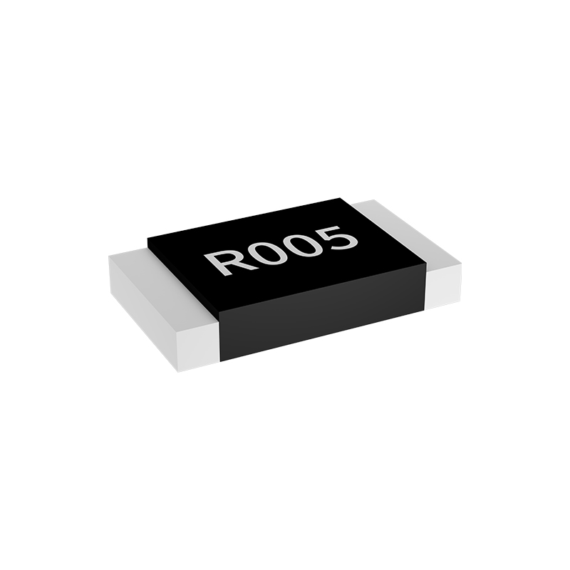
When you start pushing a circuit beyond the breadboard stage, resistor choice stops being a matter of grabbing whatever is in the drawer. Thin-film and metal-film parts earn their place in real designs because they don't drift after a few thermal cycles the way some cheap carbon films do. A 1% tolerance metal-film resistor with a 50 ppm/°C temperature coefficient will keep a feedback network stable even when the enclosure heats up, and the noise floor stays low enough that you won't spend a week chasing phantom glitches. The trick is matching the resistor's inherent strengths to the stresses the board will actually see—not just the nominal value on the schematic.
For circuits that demand repeatable performance over years, metal-foil resistors remain the quiet overachievers. Their temperature coefficient can dip below 1 ppm/°C, which matters when a precision voltage reference or a strain-gauge bridge has to hold its calibration through winter and summer. Wirewound parts, often dismissed as old-fashioned, still shine in high-power or pulse-handling roles because their bulk construction absorbs energy spikes that would vaporize a thin film. I've seen a 5-watt wirewound resistor survive repeated inrush surges that turned a thick-film part into a small crater.
Thick-film resistors get a bad reputation for drift, but used with some design discipline they are perfectly serviceable in mass-produced gear. Derating them to half their rated power and keeping them away from board edges where mechanical stress concentrates goes a long way. The real shortlist for a practical engineer is often a mix: metal foil for the precision nodes, wirewound for the abuse, and decent metal film for everything in between. That approach beats chasing a single perfect resistor that doesn't exist.
Matching Resistance Values to Current Ranges Without the Usual Trial and Error
Choosing a sense resistor for a current range usually starts with two hard limits: the maximum acceptable voltage drop at full-scale current and the resistor's power rating. Instead of swapping parts until something works, set a target drop—often 100 mV or 250 mV for low-side sensing—then divide that by the maximum current. If the range is 0–2 A and you want 200 mV at 2 A, the resistance is 0.1 Ω. That immediately fixes the value, no guesswork involved.
Next, check the power dissipation at the top of the range: I²R. For 2 A through 0.1 Ω, that's 0.4 W. Use a resistor rated at least twice that, or pick a larger package if thermal drift matters. Also verify the sense voltage at the low end of the range; with an amplifier gain of 50, 200 mV becomes 10 V, which may exceed a 5 V ADC input. Scaling the resistor downward or lowering the gain keeps the output within the converter's span without iterating on the bench.
Tolerance and temperature coefficient then refine the choice. A 1% resistor at 0.1 Ω gives a ±2 mA equivalent error at 2 A if the rest of the chain is ideal, but a 100 ppm/°C tempco can add another ±0.8 mA over a 40°C swing. Matching the value to the current range is less about finding a magic part and more about solving for resistance, checking power and signal levels, then confirming the error budget—steps that are all deterministic.
Why Some Low-Ohm Resistors Drift Less When the Heat Is On
Heat often pushes standard resistors toward permanent value shifts, but low-ohm types can sidestep much of that drift. Their resistance elements are typically thicker or wider to handle higher current densities, which gives them a larger thermal cross-section. That extra mass slows the rate of temperature change inside the element itself, reducing the thermal gradients that mechanically stress the resistive film or foil. Less localized stress means fewer micro-cracks and less permanent deformation as the part cycles through hot and cold states.
Material choice matters just as much. Many precision low-ohm resistors rely on bulk metal foils or thick-film alloys with extremely low temperature coefficients of resistance, often in the single-digit ppm/°C range. Because the total resistance value is small, the absolute change in milliohms for a given temperature swing stays tiny. A 1 mΩ resistor with a 10 ppm/°C TCR shifts only 0.01 μΩ per degree Celsius—far below the noise floor of most circuits. That inherent low absolute sensitivity to temperature is a core reason why these parts hold their value under load.
There's also a geometric and interface advantage. Low-ohm resistors frequently use four-terminal Kelvin connections, which remove the contribution of lead and contact resistance from the measured value. When the part heats up, solder joints and internal interfaces may change resistance by a few hundred microhms, but those changes fall outside the sensing path in a Kelvin configuration. The resistor's own element, being robust and low-TCR, then contributes almost nothing to drift. The result is a device that keeps its specified resistance even when surface temperatures climb well past comfortable levels.
Practical Picks for Measurement Front Ends That Need to Stay Quiet
When you need a quiet measurement front end, the first real choice isn't the lowest voltage-noise op amp on the datasheet. Source impedance flips the ranking order. A bipolar-input part with 1 nV/√Hz can easily generate 10 nV/√Hz of combined noise if its current noise flows through a 10 kΩ source. For high-impedance sensors, a JFET or CMOS input stage often wins, not because it looks better in a headline spec, but because its vanishingly small current noise keeps the total error flat.
Low-frequency drift and 1/f noise are the next quiet killers. A chopper-stabilized or zero-drift amplifier removes the slow wander almost completely, which is a lifesaver for strain gauges, thermocouples, and precision current shunts. But those parts inject small charge glitches at the input. A simple RC snubber right at the pins, sized for the source impedance, usually tames the spikes without adding meaningful thermal noise. It's a cheap fix that keeps the measurement floor clean instead of chasing it with software averaging.
The board itself is often the loudest component in the front end. Keep input traces short and far from switching regulators or clock lines. A guard ring around a high-impedance node stops surface leakage from turning into low-level wander, and a pi filter on the supply line costs pennies while blocking a surprising amount of coupled ripple. Before trusting any simulation, short the input and measure the real noise floor. If that baseline isn't below your target by a comfortable margin, no amount of post-processing will recover the signal.
What We'd Actually Install for Reliable Current Feedback in Tight Spaces
When panel depth shrinks to the point where a standard donut CT won’t clear the wireway, we skip the bulky split-core options and reach for a low-value shunt paired with a current-sense amplifier that fits on the PCB between terminal blocks. A 0.5 mΩ metal-alloy resistor in a 1206 or 2512 package handles the dissipation without derating, and the amplifier’s fixed gain keeps the signal clean enough for a 12-bit ADC even when the motor leads are less than 10 mm from the connector.
For channels where we can’t afford the voltage drop or the board heating, the fallback is a closed-loop Hall sensor in the smallest SMD footprint we can find—usually an SOIC-8 with integrated primary conductor. It doesn’t need a magnetic core around the wire, so it tucks next to the terminal strip without forcing a re-route of the high-current traces. We’ve also had good luck with side-by-side Kelvin sensing on a four-terminal shunt when the layout leaves only a narrow strip near the return path.
The trick isn’t picking the best sensor on paper; it’s checking what actually survives the hot spot next to a 40 A relay and still gives stable offset drift after a thermal cycle. We usually test the shunt at full load for 20 minutes, pull the board, and measure the resistance shift before trusting the feedback loop.
FAQ
A low temperature coefficient of resistance (TCR), tight tolerance, and stable long-term drift are the main factors. Metal alloy and metal foil types usually outperform thick film in these areas, especially when the sense voltage is small.
Values between 1 mΩ and 100 mΩ are common. Low resistance keeps voltage drop and power loss low, but you need enough signal for your amplifier. For sub-amp currents, 10 mΩ to 50 mΩ often works well.
Self-heating changes the resistor's temperature, which shifts its resistance if TCR is high. Choosing a part with a wide terminal design or low thermal resistance helps dissipate heat and keeps the reading stable.
A Kelvin layout separates the current path from the voltage sense path. This removes voltage drops from PCB traces and solder joints, so you measure only the voltage across the resistor element itself.
In most precision applications, yes. Dedicated parts have lower TCR, better surge tolerance, and more predictable resistance under load. Standard thick film may be cheaper, but it can drift noticeably with temperature and time.
0805, 1206, and 2512 are widely used. For higher power, 2512 or larger metal plate types are common. If space is extremely tight, 0603 current sense parts exist but usually handle less power.
Look for high pulse tolerance, low inductance, and a resistance value that keeps peak voltage drop below your amplifier's input range. Metal plate resistors in 2512 or 4527 sizes often handle motor inrush currents well.
Metal alloy parts offer very low resistance with good surge capability, making them ideal for high-current paths. Metal foil resistors provide extremely low TCR and excellent long-term stability, which suits precision instrumentation and calibration circuits.
Conclusion
When every millivolt counts, the choice of current sensing resistor isn't about grabbing a low-ohm part off the shelf. It's about reading the datasheet for temperature coefficient (TCR), thermal EMF, and long-term stability. A 0.5% tolerance may sound tight until a few degrees of self-heating adds back more error than the tolerance band. The shortlist here favors metal alloy and metal foil resistors over thick film, because they hold their value when the board gets warm and don't generate noisy junctions under small DC offsets. You'll also want to check the package size against the sense voltage—too large a resistor and you lose signal, too small and you cook it.
Matching resistance to current range doesn't require trial and error if you start with target burden voltage: 10 mΩ for 5 A gives 50 mV, which is plenty for a 12-bit ADC while keeping power at 0.25 W. When the heat is on, low-ohm parts with copper or manganese alloy elements drift far less than nickel-chromium, so your feedback loop stays predictable. For measurement front ends that need to stay quiet, avoid wirewound resistors with high inductance unless you compensate; instead pick a four-terminal metal element with kelvin connections. In tight spaces, a wide-terminal 2512 or 1206 with low height beats a through-hole part, and you can mount it close to the shunt traces to reduce loop area. The actual picks we'd install include a 10 mΩ 1 W 50 ppm/°C metal strip for mid-range currents, a 5 mΩ 2 W for higher loads, and a 100 mΩ 0.5 W for low-current precision—all with kelvin terminals and rated for their thermal path, not just nominal power.
Contact Us
Contact Person: Yuying Gao
Email: [email protected]
Tel/WhatsApp: +86 18926013721
Website: https://en.milliohm.net/