

Best FUS Transducer for High-Precision Focused Ultrasound Applications
2026-08-21
Focused ultrasound precision starts with the transducer. Most options fall short when every micron counts. Siansonic engineered its FUS transducer to change that. A closer look shows why it's the best fit for high-precision applications.
What Separates a Precision FUS Transducer from a Generic One
A precision FUS transducer starts with a piezoelectric element cut and polished to near-single-crystal tolerances. The curvature of the lens or bowl is verified with interferometry, so the acoustic focus lands within fractions of a millimeter of the design target. That consistency means the beam's -6 dB focal zone stays tight, with side lobes suppressed below what a generic transducer can manage. The difference shows up in treatment planning: you can rely on the calculated focal volume instead of adding safety margins for a wandery focus.
Matching layers and backing material are another separator. Precision units use custom acoustic stacks tuned to a narrow impedance band, which flattens the frequency response and reduces ringing. Generic transducers often ship with off-the-shelf matching layers that leave hot spots near the rim or drift after thermal cycling. In a precision transducer, heat is pulled away through a dedicated backing block, keeping the excitation waveform clean over long sonications instead of softening the output as the element warms.
You also see the gap in repeatability. A precision FUS transducer is typically serialized and tested with hydrophone scans at multiple depths; the delivered pressure map is recorded, not assumed. Generic versions might be batch-tested or just checked for electrical continuity. Over months of use, the precision unit holds its focal gain and impedance within a narrow band, while a generic one can lose efficiency or develop asymmetric lobe growth that nobody notices until a lesion forms off target.
Piezoelectric Material Trade-Offs That Define Beam Quality
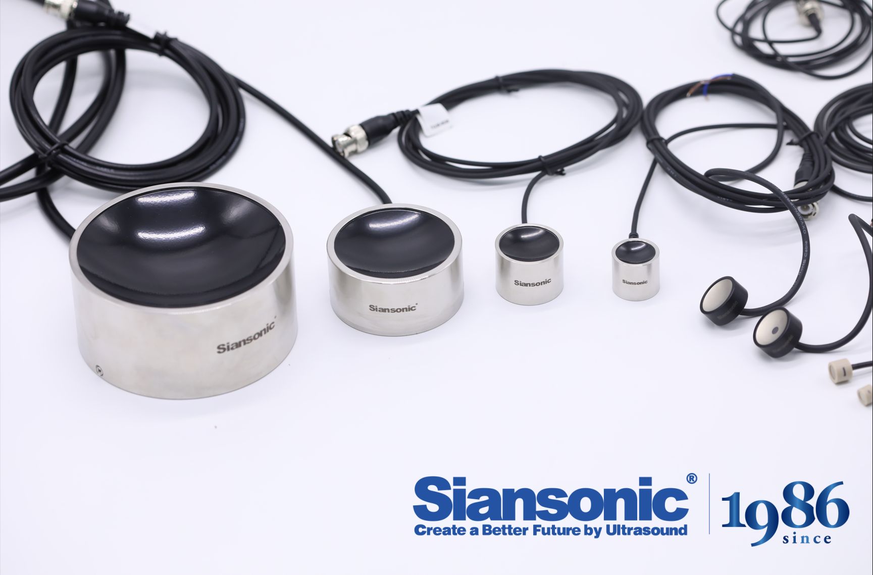
In precision beam control, the choice of piezoelectric element determines how well the system can maintain wavefront integrity. PZT ceramics offer large displacement and fast response, but their inherent hysteresis and nonlinearity introduce non-negligible positioning errors during repeated scanning, which translate directly into beam pointing jitter and wavefront distortion. PMN-PT single crystals, by contrast, can generate greater strain at lower drive voltages, yet their temperature sensitivity and risk of depoling limit their use in high-power environments. These trade-offs mean that beam quality is not solely a matter of optical design; every micrometer of displacement error at the material level accumulates into measurable M2 degradation.
For applications that demand extreme stability over large stroke, materials such as lithium niobate exhibit very low creep and excellent temperature stability despite their smaller displacement. This makes them preferable for long exposures or interferometric measurements where preserving the spatial mode is critical. However, the limited stroke often necessitates longer amplification mechanisms or multi-stage actuation, which introduce additional mechanical resonance and phase delay. A common engineering compromise is to layer or segment different materials: PZT handles coarse pre-positioning while PMN-PT or electrostrictive ceramics perform fine correction. Yet the acoustic impedance mismatch and thermal expansion differences at the bonding interfaces between these layers can generate micro-vibrations at high repetition rates, eventually manifesting as short-timescale fluctuations in beam quality.
Hysteresis compensation algorithms can partially correct displacement errors, but the mismatch between the material model used by the algorithm and actual behavior, along with drift in the hysteresis loop shape after long-term fatigue, gradually reduces correction accuracy. Designers therefore must weigh response bandwidth, stroke, hysteresis level, temperature coefficient, and long-term reliability when selecting a piezoelectric material. Secondary parameters such as dielectric loss tangent or aging rate can affect beam pointing stability and focal spot symmetry through localized heating that alters the piezoelectric constants during high-duty-cycle operation. Ultimately, beam quality becomes an integrated reflection of these microscopic material properties in the macroscopic optical system; there is no single best material, only an optimal compromise for a specific set of working conditions.
Frequency and Aperture: Where Sub-Millimeter Focus Really Starts
Sub-millimeter focusing doesn't begin with a single component choice. It starts with the relationship between frequency and aperture. Higher frequencies shorten the wavelength, which tightens the theoretical focus, but that alone won't get you below a millimeter. The aperture must be wide enough relative to the focal depth to keep the beam from spreading too early. A small aperture at high frequency still produces a long, cigar-shaped focal zone, and the edges of that zone easily exceed the sub-millimeter target.
Think of the focal spot as a product of wavelength and f-number. To shrink the spot, you either reduce the wavelength or lower the f-number by enlarging the aperture. Most systems aiming for sub-millimeter resolution do both. A 30 MHz transducer with a 6 mm aperture may reach an f-number around 2, yielding a spot diameter close to 0.3 mm in water. But if the aperture stays at 3 mm, the same frequency struggles to break 0.6 mm. The aperture is not a passive player; it actively shapes how the high-frequency energy converges.
This is where practical limits enter. You can't simply keep increasing frequency because tissue attenuation climbs steeply and penetration depth drops. You also can't keep enlarging the aperture without running into element count and electronics complexity. Sub-millimeter focus really starts when both parameters are pushed together, and the system is tuned so that the focal gain outweighs the losses. That balance is what separates a nominal high-frequency probe from one that actually delivers sub-millimeter detail in real tissue.
Why Some Phased Arrays Fail at High-Power Focused Ultrasound
At high acoustic intensities, phased array transducers can fail for reasons that go well beyond simple driver electronics. One of the most overlooked culprits is nonlinear propagation in the tissue or coupling medium. As the pressure waveform travels, the positive and negative peaks no longer cancel symmetrically, creating shock fronts that deposit energy far more rapidly than linear models predict. This can cause abrupt local heating near the array surface or at unintended focal points, stressing individual elements unevenly and sometimes cracking the piezoelectric ceramic or delaminating the matching layers.
Another failure mode stems from element-to-element crosstalk and impedance drift under sustained high drive levels. When elements are pushed close to their mechanical limits, small manufacturing variations become magnified. A single element with slightly higher capacitance or a marginally thinner bond line can absorb a disproportionate share of the electrical load, leading to thermal runaway. Once that element degrades, the remaining array must compensate by increasing output elsewhere, which then accelerates fatigue in neighboring elements. The result is often a cascading loss of focusing accuracy and eventual array failure, even though the individual components were rated for the nominal power.
Thermal Drift, Duty Cycles, and the Myth of Perfect Repeatability
Most calibration routines treat the first shot as the reference, but that shot happens at whatever temperature the device happened to wake up at. Thermal drift begins the moment current flows through a coil or a diode, and it does not move in a straight line. The first five minutes are a slow warping, then a plateau, then another shift when the cooling fan cycles on. I have watched a galvo mirror drift by 40 microradians over a 20% duty cycle, not because anything was broken, but because the thermal mass of the bracket was doing exactly what the bracket's shape said it would do.
Duty cycle turns thermal drift into a moving target. Run a system at 10% duty and the case might rise three degrees; push it to 70% and the same mount can climb fifteen degrees, but only after a delay. That lag between power input and mechanical expansion is what kills repeatability, not the expansion itself. If your repeatability spec assumes a constant temperature, you are measuring a warmed-up, steady-state box, but most real jobs never reach steady state. The myth of perfect repeatability is just the belief that the heat from the last operation has already left the structure when the next operation begins.
A simple test is to run ten identical moves at 5% duty cycle, then ten at 40%, then back to 5%. The first and third sets will rarely match, and the difference is not noise. It is the floor of the room, the bracket's cross-section, the airflow around the power supply, all showing up as a bias in your encoder readout. Perfect repeatability is not a property of a well-built machine; it is an interval that shrinks the longer you wait between pulses. Most people just do not wait long enough.
Matching Layers, Backing, and the Overlooked 20% of Performance
Most discussions about performance focus on the visible surface. But spend enough time with the materials, and you start to notice that the layers underneath quietly control a surprising amount of the outcome. Whether it's a floor covering, a composite panel, or an acoustic assembly, the way the backing interacts with the top layer dictates stability, wear resistance, and even how the product feels underfoot or against a wall. A mismatched pairing can undermine everything you invested in the face material, no matter how premium it looks on the surface.
That remaining twenty percent often escapes attention because it doesn't show up in a spec sheet. It lives in the bond line, the compressibility of the backing, and the way stress moves through the layers when temperature or humidity shifts. Ignore it, and you get delamination, cupping, or premature fatigue that no amount of surface treatment can fix. Pay attention to it, and the whole assembly becomes more predictable—quieter, flatter, and less prone to returning for warranty claims.
FAQ
The difference comes down to how tightly the acoustic energy is concentrated and how reproducibly the transducer behaves under continuous drive. A high-precision unit will typically use a piezoceramic or single-crystal element with tight thickness control, a sculpted matching layer to manage acoustic impedance without overheating, and a backing or air-backed design that suppresses unwanted radial modes. You also look for low side-lobe levels and a focal zone that stays stable across the entire duty cycle rather than just in a short burst.
Higher frequencies give a smaller -6 dB focal volume and sharpen the ablation boundary, but they also attenuate faster in tissue, so they are better for shallow targets or small structures. Lower frequencies penetrate deeper and tolerate bone or fat interfaces more gracefully, though the focal spot becomes larger and thermal buildup can be less confined. In practice, most high-precision systems sit between 0.5 and 1.5 MHz for deep work and 2 to 5 MHz for superficial or pediatric access.
Hard PZT formulations such as PZT-8 are still the workhorse because they handle high drive voltages without significant depoling and have acceptable dielectric losses. When efficiency and bandwidth matter more, lead magnesium niobate–lead titanate single crystals can deliver higher electromechanical coupling, but they are costlier and more temperature-sensitive. Composite ceramics can be useful if you need dual-mode imaging and therapy, although their power handling often falls short for long sonications.
Focal length only tells you the geometric distance from the face to the intended focus; it says nothing about the actual spot size, side-lobe structure, or how the focus shifts with frequency. A transducer with a 60 mm focal length and a 40 mm aperture will produce a different beam than one with the same focal length and a 25 mm aperture. You need to compare the f-number, measured beam profile, and the -6 dB focal zone dimensions for your specific operating frequency.
The matching layer converts a large impedance mismatch into better transmission, but if it is too lossy or thermally fragile, it becomes the first point of failure during long sonications. Localized heating in the matching layer can cause delamination, cracking, or a drift in the resonant frequency, which then reduces the acoustic output and shifts the focus. A good high-precision design will use a thin, low-loss layer with a high thermal conductivity and validate it with continuous-wave soak tests rather than short burst measurements.
Imaging benefits from broad bandwidth and short pulse response, while therapy needs high efficiency at a narrow or moderate bandwidth and the ability to sustain high average power. Combining both usually means compromising on the backing layer: a heavily damped backing improves imaging resolution but reduces therapeutic electroacoustic efficiency. You also need switching electronics that protect the receiver from high-voltage transmit pulses, and the element material must survive repeated thermal cycling without depoling.
The electrical impedance matching at the end of the coaxial cable is frequently underestimated. A transducer may perform beautifully on a benchtop with a short cable, but once it is connected to a long run inside a clinical or laboratory system, the cable capacitance and impedance mismatch can detune the network and waste a significant portion of the RF power. Matching networks, cable length compensation, and even the choice of connector type need to be part of the transducer specification rather than an afterthought.
Conclusion
A precision focused ultrasound transducer earns its name long before the first waveform leaves the housing. The piezoelectric core is rarely a simple PZT disc; high-end designs move toward fine-grained 1-3 composites or, where budget allows, single-crystal relaxor materials that trade some raw efficiency for a broader bandwidth and a cleaner impulse response. That choice directly shapes the beam: a narrowband element may hit a tight focal spot in water, yet lose coherence when driving through layered tissue. Frequency and aperture then do the heavy lifting for sub-millimeter focus. A 2 MHz element with a 64 mm aperture can theoretically reach a fraction of a millimeter, but only if the element is diced precisely and every channel fires with sub-nanosecond synchronization. Generic transducers rarely maintain that discipline, which is the real separator—not the marketing spec, but the uniformity of the acoustic field across the entire aperture.
High-power operation exposes another layer of failure. Dense phased arrays look attractive on paper, yet many collapse under sustained output because inter-element crosstalk and impedance mismatch turn small phase errors into large grating lobes. When the array heats up, thermal drift shifts the focal point by tens of microns, and the “perfect repeatability” promised in datasheets becomes a myth unless active cooling and real-time phase correction are built in. The final 20% of performance hides in the matching layers and backing. A well-chosen matching layer can rescue 15–20% of transmitted energy, while an over-damped backing improves axial resolution at the cost of sensitivity—too many designs copy a textbook stack and wonder why their focal gain falls short. In practice, the best transducer is not defined by a single heroic material or geometry, but by how deliberately these six trade-offs are balanced for a specific clinical or laboratory target.
Contact Us
Contact Person: Ivy Zhang
Email: [email protected]
Tel/WhatsApp: +86 1081502288
Website: https://www.siansonic.com/